Proposed System:
- Reduce the more area coverage and power consumption level of the architecture.
Advantages:
- Reduce the complexity of hardware implementation
- Reduce the size
Software used:
- Modelsim
- Xilinx

₹20,000.00 Original price was: ₹20,000.00.₹10,000.00Current price is: ₹10,000.00.
Source Code : VHDL
Abstract:
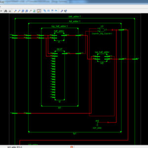
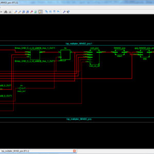
A novel low-complexity multiple-input multiple-output (MIMO) detector tailored for single-carrier frequency division-multiple access (SC-FDMA) systems, suitable for efficient hardware implementations. The proposed detector starts with an initial estimate of the transmitted signal based on a minimum mean square error (MMSE) detector. Subsequently, it recognizes less reliable symbols for which more candidates in the constellation are browsed to improve the initial estimate. The proposed architecture of this paper analysis the logic size, area and power consumption using Xilinx 14.2.
List of the following materials will be included with the Downloaded Backup:
Proposed System:
Advantages:
Software used:
₹16,000.00 Original price was: ₹16,000.00.₹10,000.00Current price is: ₹10,000.00.


₹15,000.00 Original price was: ₹15,000.00.₹6,000.00Current price is: ₹6,000.00.
Copyright © 2024 Nxfee Innovation.
A High-Throughput VLSI Archite...
₹20,000.00 Original price was: ₹20,000.00.₹10,000.00Current price is: ₹10,000.00.
Reviews
There are no reviews yet.