Proposed System:
- To Increases the number of tap in the FIR filter upto 32, and reduce the power consumption.
Advantages:
- Reduce the power level
- Increases the efficiency
Software implementation:
- Modelsim
- Xilinx

₹14,000.00 Original price was: ₹14,000.00.₹10,000.00Current price is: ₹10,000.00.
Source : VHDL
Abstract:
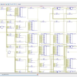
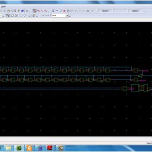
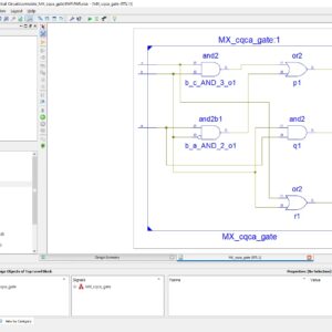
Transpose form finite-impulse response (FIR)filters are inherently pipelined and support multiple constant multiplications (MCM) technique that results in significant saving of computation. However, transpose form configuration does not directly support the block processing unlike direct form configuration. In this paper, we explore the possibility of realization of block FIR filter in transpose form configuration for area-delay efficient realization of large order FIR filters for both fixed and reconfigurable applications. Based on a detailed computational analysis of transpose form configuration of FIR filter, we have derived a flow graph for transpose form block FIR filter with optimized register complexity. A generalized block formulation is presented for transpose form FIR filter. We have derived a general multiplier-based architecture for the proposed transpose form block filter for reconfigurable applications. A low-complexity design using the MCM scheme is also presented for the block implementation of fixed FIR filters. The proposed structure involves significantly less area delay product (ADP) and less energy per sample (EPS) than the existing block implementation of direct-form structure for medium or large filter lengths, while for the short-length filters, the block implementation of direct-form FIR structure has less ADP and less EPS than the proposed structure. The proposed architecture of this paper analysis the logic size, area and power consumption using Xilinx 14.2.
List of the following materials will be included with the Downloaded Backup:
Proposed System:
Advantages:
Software implementation:

₹10,000.00 Original price was: ₹10,000.00.₹6,000.00Current price is: ₹6,000.00.


₹20,000.00 Original price was: ₹20,000.00.₹10,000.00Current price is: ₹10,000.00.
Copyright © 2024 Nxfee Innovation.
A High Performance FIR Filter ...
₹14,000.00 Original price was: ₹14,000.00.₹10,000.00Current price is: ₹10,000.00.
Reviews
There are no reviews yet.