
Proposed Title :
Low Power and Low Cost Thermal Energy Harvesting Power Supply with an Internal Start up Circuit with regulator for Pacemakers
Proposed System:
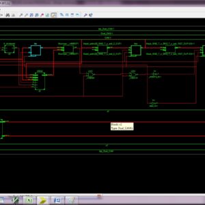
- In proposed system design is TE energy harvesting system with regulator.
- Design this architecture at 130nm level.
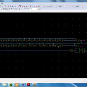
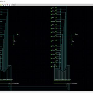
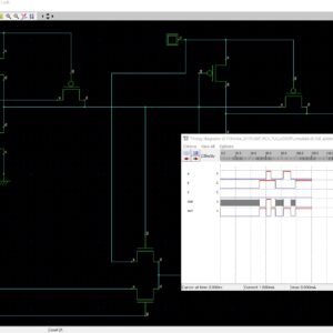
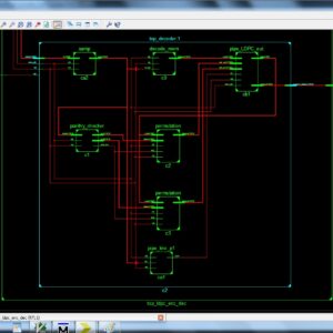
Software implementation:
- TANNER


Reviews
There are no reviews yet.