Existing System:
Compressors are the digital circuits which have the capability to add five/six/seven bits at a time and hence called as column compressors. A typical five input compressor is illustrated in this brief. It takes 4 regular inputs and 1 intermediate carry-in input and generates 1 sum bit, 1 carry-out bit and another intermediate carry bit. Intermediate carry bits are the carry-in and carry-outs
(called as horizontal carry propagation) from previous and to next stage compressors. Carry-out (also called as vertical carry) bit is final carry generated along with the sum bit.
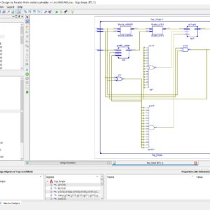
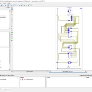
Since compressors forms the basic and critical components for multipliers and large-input adders, several compressors architectures were developed in the past to address several constraints. Some of the compressor architectures described in the past are shown in Fig. 4 & Fig. 5.
Compressor architecture shown in Fig. 4 is built using the full-adders. This architecture has only two cells and will have minimum interconnects but each of the cell needs to generate the sum and carry path and one of the path is dependent on the other. This requires larger drive strength to drive the chain of compressors and hence the power consumption will be higher. The higher drive strength will significantly have the reduced delay.
Fig. 5 shows the compressor architecture built using lesser fan-in gates. Logic implementation with lesser fan in gates leads to more number of interconnects which has significant impact on glitch power & delay. In lower technological nodes the interconnect power is dominant than the gate power, hence the architecture of leads to high power consumption.
Disadvantages:
- Area coverage is high
- Power consumption is high
Proposed System:
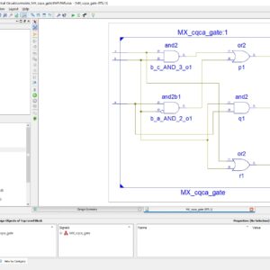
Fig. 6 shows the proposed compressor architecture. The proposed compressor architecture is built with larger fan-in gates and also using separate logics for sum and carry paths. In the sum path four 2 input XOR cells are replaced by two 3 input XOR cells and in the carry path two 2
input AND cells & one 2 input OR cells are replaced by one 6 input AND-OR (AO222) logic cell. Larger fan-in gates covers large part of the logics and helps in minimizing the number of gates required for implementation. Lesser gates lead to smaller area and minimum interconnect delays. Thus the proposed compressor architecture helps in reducing the power consumption.
Thus the proposed compressor architecture enables new features like design specific/constraint specific architectures and allows utilizing for low power applications. Optimizations provided in the proposed architectures are,
- Minimum interconnect in sum-path reduces the interconnect delay and associated glitches
- Reduced power consumption with minimum interconnects
- Independent carry logic to reduce the horizontal carry delay
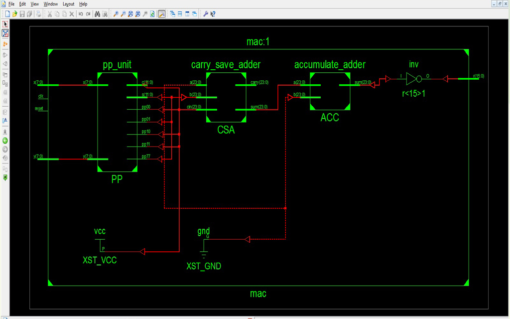
The proposed two’s complement MAC architecture is shown in Fig. 7. Compared to the basic architecture in Fig. 7, the new design replaces the final adder in the first stage with a carry-save adder in the second. The MAC architecture’s critical path delay still depends on the PP unit, but the delays of the two stages are now similar. The second stage remains faster, especially for larger operand sizes, which allows the accumulate adder to accommodate more guard bits.
Our MAC architecture offers a number of advantages in terms of latency, speed, area, power, and energy.
- The proposed MAC architecture needs no final adder.
- our architecture allows us to remove not only the final adder but also one pipeline register level—and the corresponding clock power—without degrading speed.
- Because our architecture is smaller, it uses shorter interconnects.
Advantages:
- Area coverage is reduced
- Power consumption is reduced
Reviews
There are no reviews yet.