Description
Existing System:
RAISING the level of abstraction in VLSI design has some distinct advantages over traditional register-transfer level (RTL) design methods. First, most of the designs start with a high-level model in order to validate the application to be implemented. High-level synthesis (HLS) provides a direct path between these models and RTL. It has been shown [1] that one line of C-code translates into 7–10× more gates than RTL. This further implies that behavioral descriptions are easier to maintain and debug, and that fewer bugs will be introduced by designers. Second, in many cases, the design specifications are unstable and any changes in them can lead to major architectural changes (e.g., the use of on-die memory or external memory). At the RTL, this requires major redesigns, while at the behavioral level; these changes can be tackled easier. Third, raising the level of abstraction allows software and hardware designers to speak the same language. Applications to be implemented in custom hardware are getting extremely complex and are based on complex mathematical models that in many cases are difficult to understand by the hardware designer. Using the same behavioral description language allows both hardware and software designers to communicate at the same level of abstraction using the same language. Some examples of complex applications include dedicated hardware security engines based on complex encryption and decryption algorithms.
Disadvantages:
- Performance is low
Proposed System:
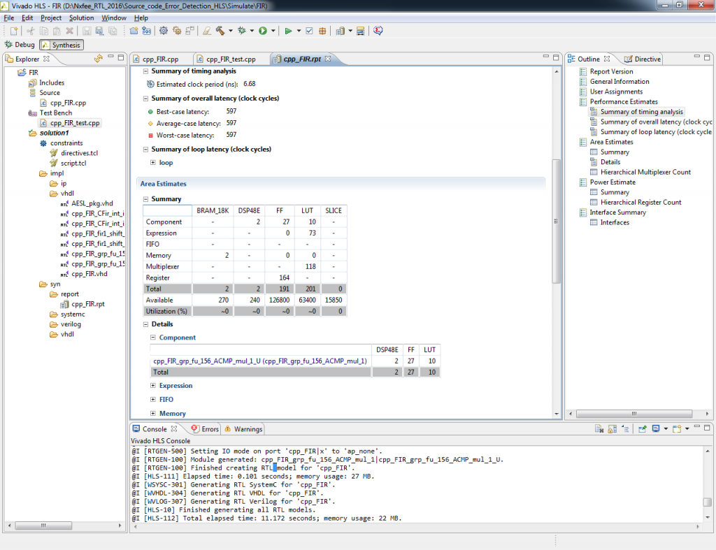
Our proposed verification method takes as inputs a behavioral description in ANSI-C and the untimed test vectors used for the SW verification. Fig. 1 shows an overview of the complete flow. It comprises of four main steps. An alternative initial preprocessing step is also part of the flow. This preprocessing step parses the given behavioral description and performs typical compiler optimizations (e.g., dead code elimination and constant propagations). The output of this preprocessing step is the optimized behavioral description called ANSI-C optimized (ANSI-CO). The advantages of executing this initial step are obvious. Our method cannot automatically, e.g., detect dead code, which means that it would insert probes to visualize parts of the code, which are not needed. The drawback of executing this preprocessing step is that the optimized C code is automatically generated by the HLS tool parser and is, therefore, not as readable as the original C code written by the designer. Moreover, the errors detected by our method will consequently point to the ANSI-CO code and not to the original code (ANSI-C).
Probe Insertion
One of the main contributions of this paper is to determine how and where to insert the probes shown in Fig. 2 and also the type of probe. A naïve method inserts a probe whenever an internal signal is being written to. This approach guarantees that the EDL is minimized at the expense of having to record and compare a very large number or probes. The number of probes inserted is important in order to exactly locate where the mismatch between the original behavioral description’s behavior and the synthesized descriptions happen. In order to determine the quality of the error detection mechanism, we define the term SCED.
Observations
At this point, some observations should be made. First, most HLS tools perform automatic bitwidth optimization. This means that the final bitwidth of the internal signals is not known when the probes are inserted and hence the probes’ bitwidth will be larger or equal to the internal signals’ bitwidth after HLS. Two cases should be considered.
- The HLS tool also adjusts the output port bitwidth automatically and hence there is nothing to be done.
- Our method checks if the internal signal is signed or unsigned and inserts a type cast at the assignment, e.g., probe = (signed) internal_signal or probe = (unsigned) internal_signal.
FIR filter:
HLS tools can very easily create these signals because they know in which particular state the inputs are read and in which states the outputs are generated. Fig. 3 shows an example of valid signals. Fig. 3(a) shows the block diagram of a finite-impulse response (FIR) filter with its data and coefficient ports and the data out port. Fig. 3(b) shows the valid signals generated automatically by the HLS tool in order to assert when an input signal is needed and when a valid output is generated. This simple, but extremely effective method combined with testbenches, which monitor these signals to apply and to compare test vectors, allows a very effective way to reuse untimed input and output test vectors for timing verification. The last step in the HLS verification flow is the verification of the final RTL generated by the HLS. For this purpose, an RTL testbench generator that can again reuse the untimed original input test patterns and compare the generated outputs with the original untimed golden outputs is normally provided in commercial HLS flows. These different models generators combined with the RTL testbench generator allow designs to be effectively verified at different HLS design stages.
Advantages:
- Performance is high
Software implementation:
- Modelsim
- Xilinx ISE