Description
Existing System:
To design a reconfigurable CORDIC architecture with minimum reconfiguration overhead, we need to maximize the sharing of common hardware circuit in different configurations. Therefore, to explore the possibility of reconfigurable CORDIC, We design three reconfigurable CORDIC architectures: 1) rotation-mode reconfigurable CORDIC; 2) vectoring-mode reconfigurable CORDIC; and 3) generalized reconfigurable CORDIC.
Rotation-Mode Reconfigurable CORDIC:
The design for reconfigurable rotation-mode CORDIC (shown in Fig. 1) consists of three parts: 1) preprocessing unit; 2) reconfigurable CORDIC rotation unit; and 3) post processing unit. The preprocessing unit ensures that the input rotation angle to the CORDIC processing structure always lies in the range [0,π/4], as the maximum rotation angle that can be handled by micro rotation sequence generator is π/4. The post processing unit is required only for circular trajectory to swap/complement the sine/cosine values depending on the octant of the rotation angle. The user can control the trajectory of the reconfigurable CORDIC by changing a 1-bit signal T.
Recursive Architecture:
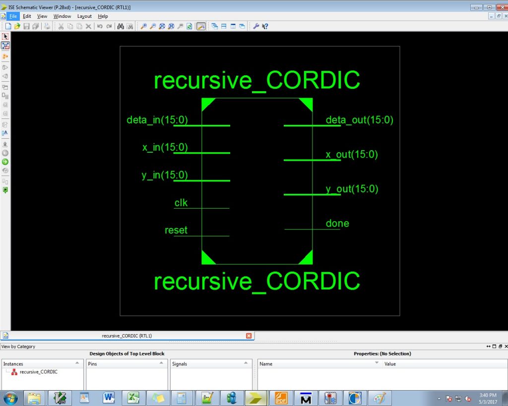
The recursive architecture (shown in Fig. 2) uses a single CORDIC microrotator to perform all the CORDIC iterations. The circular CORDIC requires one iteration less than the hyperbolic CORDIC , but here we realize the architecture for the same number of iterations (eight for s basic=2 and eleven for s basic=3) for both circular and hyperbolic trajectories. The reconfigurable coordinate calculation unit (RCCU) isshowninFig.3.
Pipelined Architecture:
Fig. 4 shows the reconfigurable CORDIC rotation unit for basic-shift 2. The shift-index si is fixed in every RCCU, and hence the shifters are hardwired and do not involve high complexity barrel-shifters. The implementation of RCCUs varies according to the basic-shift si. With slight modifications, the pipeline can be extended for basic-shift 3.
Reconfigurable Vectoring-Mode CORDIC:
The recursive architecture of Fig. 2 can be used to realize CORDIC iterations for vectoring-mode. The rollover counter value is 15 for s basic=2, and 17 for s basic=3. The pipelined architecture of vectoring-mode reconfigurable CORDIC consists of eight stages for s basic = 2, as shown in Fig. 5.
Generalized Reconfigurable CORDIC:
The generalized reconfigurable CORDIC can operate either in vectoring-mode or in rotation-mode for both circular and hyperbolic trajectories. The user can select the trajectory of operation using a single bit signal T(T=1 for circular andT=0 for hyperbolic). Another single bit signalMis used to control the mode of operation (M=0 for rotation-mode and M=1 for vectoring-mode). The recursive architecture of the proposed generalized reconfigurable CORDIC is implemented by combining the CORDIC microrotators for both rotation-mode and vectoring-mode CORDICs, as shown in Fig. 6. The throughput of the proposed recursive generalized reconfigurable CORDIC is the same as that of the recursive reconfigurable vectoring-mode CORDIC. The block diagram for pipelined generalized reconfigurable CORDIC using basic-shiftsbasic=2 is shown in Fig. 7. It can be easily extended to basic-shiftsbasic=3 as is done for reconfigurable rotation-mode and vectoring-mode CORDICs.
Disadvantages:
Delay is high
Proposed System:
The adder of the micro rotation sequence generator and reconfigurable coordinate calculation unit is creating the delay due to the conversional process. The design needed to other adder with low delay. So we select the carry skip adder for this reason. A carry-skip adder is generally made up of a simple ripple carry-adder along with a special speed up carry chain is known as a skip chain. The distribution of ripple carry blocks is defined by this carry chain, which constitute the skip adder.
Carry skip adder (CSA)
A carry-skip adder is generally made up of a simple ripple carry-adder along with a special speed up carry chain is known as a skip chain. The distribution of ripple carry blocks is defined by this carry chain, which constitute the skip adder.
Carry skip mechanism
The summation of two digits which is of binary at phase i, where i not equal to zero (i ≠ 0), The input bit carry-in (Ci) will be dependent of the ripple carry adder, which in fact is the carry-out, Ci-1 of the previous phase. Therefore, it is clear that in order to compute the sum and the carry out, Ci+1, of phase i, one should know the carry-in (Ci) in advance. In some scenarios Ci+1can be computed without the actual knowledge of Ci.
The Boolean equations of a full adder is given as,
Pi = Ai Bi
Si = Pi Ci
Ci+1 = Ai Bi + Ci Pi
Conventional carry skip adder:
The structure of an N-bit Conventional carry skip adder, which is based on blocks of the RCA (RCA blocks), is shown in Fig. 10. In addition to the chain of FAs in each stage, there is carry skip logic. For an RCA that contains N cascaded FAs, the worst propagation delay of the summation of two N-bit numbers, A and B, belongs to the case where all the FAs are in the propagation mode. It means that the worst case delay belongs to the case where
Pi =Ai ⊕Bi =1fori =1… N
Where Pi is the propagation signal related to Ai and Bi. This shows that the delay of the RCA is linearly related to N. In the case, where a group of cascaded FAs are in the propagate mode, the carry output of the chain is equal to the carry input. In the CSKA, the carry skip logic detects this situation, and makes the carry ready for the next stage without waiting for the operation of the FA chain to be completed. The skip operation is performed using the gates and the multiplexer shown in the figure. Based on this explanation, the NFAs of the CSKA are grouped in Q stages. Each stage contains an RCA block with Mj FAs (j =1… Q) And skip logic. In each stage, the inputs of the multiplexer (skip logic) are the carry input of the stage and the carry output of its RCA block (FA chain). In addition, the product of the propagation signals (P) of the stage is used as the selector signal of the multiplexer.
The proposed design of the micro rotation sequence generator and reconfigurable coordinate calculation unit is given figure 11 and 12.
Advantages:
- Less delay
Software implementation:
- Modelsim
- Xilinx ISE