FPGA Implementation of Data Encoding and Decoding Technique for Energy Consumption in NOC
Proposed System:
- In proposed system we are additionally add the decoder for scheme 3.
Software implementation:
- XILINX – HDL Implementation

₹10,000.00 Original price was: ₹10,000.00.₹6,000.00Current price is: ₹6,000.00.
Source : VHDL
Abstract:
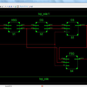
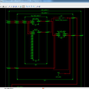
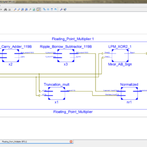
As the technology shrivel, the power dissipated by the communication subsystem, namely, the routers, NIs, and links. In this paper we are discussed about a set of data encoding and decoding schemes at goal of reduce the power consumption in links of the NoC. This proposed system is transparent and general with respect to the NoC fabric. Finally we are design the area and power efficient encoder and decoder design.
List of the following materials will be included with the Downloaded Backup:
Proposed System:
Software implementation:
₹10,000.00 Original price was: ₹10,000.00.₹4,000.00Current price is: ₹4,000.00.


₹10,000.00 Original price was: ₹10,000.00.₹7,000.00Current price is: ₹7,000.00.
Copyright © 2024 Nxfee Innovation.
Data Encoding Techniques for R...
₹10,000.00 Original price was: ₹10,000.00.₹6,000.00Current price is: ₹6,000.00.
Reviews
There are no reviews yet.