Proposed System:
- Implemented 4:2, 5:2 and 7:2 compressor using same Adiabatic
Advantages:
- Reduce the power level
- Increases the efficiency
- Reduced the area size
Software implementation:
- DSCH3/Microwind
- Modelsim
- Xilinx

₹12,000.00 Original price was: ₹12,000.00.₹6,000.00Current price is: ₹6,000.00.
Source : VHDL & Verilog HDL ( DSCH3/MICROWIND)
Abstract:
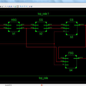
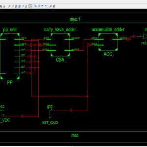
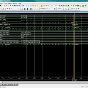
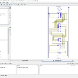
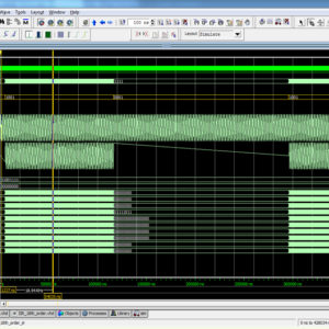
The Subthreshold adiabatic logic for Ultralow power application is a novel approach is efficient in low speed operations, where power consumption and longevity are the pivotal concerns instead of performance. Here, we are implementing the adiabatic logic gates and implementing CLA 8-bit, it will compared to the normal logic gates, the adiabatic logic makes a more power consumption and also increasing speed. The schematic and layout of a 4-bit carry look ahead adder (CLA) has been implemented to show the workability of the proposed logic. The effect of temperature and process parameter variations on sub threshold adiabatic logic-based 4-bit CLA has also been addressed separately. Post layout simulations show that sub threshold adiabatic units can save significant energy compared with a logically equivalent static CMOS implementation.
List of the following materials will be included with the Downloaded Backup:
Proposed System:
Advantages:
Software implementation:
₹20,000.00 Original price was: ₹20,000.00.₹10,000.00Current price is: ₹10,000.00.


₹20,000.00 Original price was: ₹20,000.00.₹10,000.00Current price is: ₹10,000.00.
Copyright © 2024 Nxfee Innovation.
Implementation of Subthreshold...
₹12,000.00 Original price was: ₹12,000.00.₹6,000.00Current price is: ₹6,000.00.
Reviews
There are no reviews yet.