Description
Proposed Title :
Low complexity analog technique for attenuation of LO harmonic Suppression Technique for SDR Receivers
Improvement of this Project:
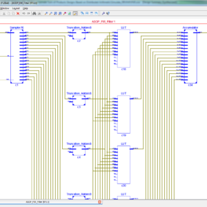
To develop a Low pass filter design using Truncation multiplier concept.
To implement this Filter design with a SDR in high-Q RF filtering resilient to out-of-band blockers for a low complexity analog technique for attenuation of LO harmonics.
Software implementation:
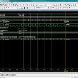
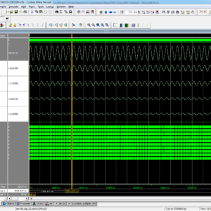
- Modelsim & Xilinx
Existing System:
SOFTWARE-DEFINED radios (SDRs) are reconfigurable systems that are able to tune to any wireless standard with variable carrier frequency, modulation type, and bandwidth. This concept is inspired by the increased demand for integrated multi standard wireless transceivers. These transceivers can support a variety of radio standards such as Global System for Mobile communications (GSM), Wi-Fi, positioning systems (GPS), Bluetooth, 3G/4G cellular, and Zigbee. The ideal SDR receiver includes a wideband analog-to-digital (A/D) converter followed by a digital signal processor (DSP) that accomplishes the radio functions. However, wideband data converters require very high-power consumption. Hence, in order to efficiently realize the SDR concept, mixed-signal and digital techniques can be utilized.
Reported techniques to realize mixed-signal or discrete-time (DT) SDR receivers usually include a mixing operation before A/D conversion. Mixing can be continuous or discrete in time. In the receiver includes a low-noise amplifier (LNA) and a continuous-time mixer, and the sampling and conditioning of the . sampled signal are realized after the down conversion at zero-IF. Several approaches use RF sampling with DT mixing. One example of this approach is proposed in where the RF signal voltage is oversampled and multiplied by the oversampled local oscillator (LO) waveform for down conversion. Nowadays, direct sampling of an RF signal can be realized in highly scaled CMOS. Different RF-sampling receiver architectures are proposed in working at different sampling frequencies, with different subsequent DSP techniques.
This paper presents an SDR front end with high-Q RF filtering resilient to out-of-band blockers and proposes a low complexity analog technique for attenuation of LO harmonics. This technique can be mixed with already available DT mixing techniques to improve their harmonic rejection.
Disadvantages:
- It presents the SDR receivers for high complexity analog technique for attenuation of LO harmonics.
- Achieves a lower performance of SDR receivers.
- Efficiency is Low.
Proposed System:
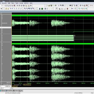
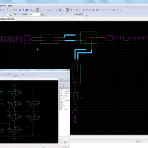
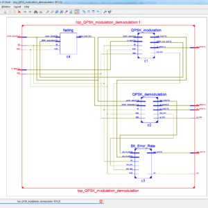
Software Defined radios (SDRs) are reconfigurable systems that are able to tune to any wireless standard with variable carrier frequency, modulation type, and bandwidth. This concept is inspired by the increased demand for integrated multi standard wireless transceivers. This paper proposes the SDR front end with high-Q RF filtering resilient to out-of-band blockers and low complexity analog technique for attenuation of LO harmonics. The transconductance can be modulated by the (LNTA) low-noise transconductance amplifier with a raised-cosine signal. Thus, the effective attenuation of the LO harmonics is achieved. Removing any RF pre filtering causes several problems includes wideband noise and large blockers that can directly leak into the receiver. Therefore, the proposed system presents the SDR receivers for low complexity analog technique for attenuation of LO harmonics. This achieves a better performance of SDR receivers. Finally, this technique is implemented in the VHDL and synthesized in the XILINX and shown the comparison in terms of area, power and delay comparison.
Software-Defined Radios And Their Limitations Due To Blockers And Lo Harmonics
This section overviews the SDR concept and discusses its limitations due to the blockers and interferers at the LO harmonics. The traditional narrowband radios include fixed high Q external surface acoustic wave (SAW) filters that remove out-of-band blockers, images, and interferers. Blockers can desensitize the receiver, while images and interferers can be down converted to IF or baseband corrupting the desired signal. In a portable battery-powered handheld wideband SDR device, it is not easily possible to use SAW filters. Hence, the research focus in recent years has been noticeably focused on SAW-less wideband receivers. These receivers are software-defined for various standards, bandwidths, and frequencies. Removing any RF pre filtering causes several problems: wideband noise and large blockers that can directly leak into the receiver. Moreover, during down conversion, any unwanted signal located in LO harmonic frequencies can be easily aliased with the wanted signal at the baseband. Therefore, there are two main issues in the design of any wideband receiver front end, as depicted in Fig. 1, which must be considered: out-of-band blockers high-Q filtering to avoid gain compression, and LO harmonics rejection of the mixer to avoid aliasing.
Blockers
For a typical receiver, a wanted channel signal needs to be received at very low amplitude. Therefore, the receiver’s LNA must operate at a relatively-high gain. For instance, if the gain of the LNA is equal to 20 dB, a 0-dBm out-of band blocker results in a 632-mV blocker (assuming a 50- system). This is amplified to 6.3 V and completely compresses the receiver. Hence, without external filtering, on-chip high-Q filtering is required.
Four techniques are proposed in the literature to address blockers: translational filtering, mixer-first technique, current-mode systems, and voltage-mode system with RF filtering. Recent work presenting a voltage-mode system with RF filtering includes a linear LNA that amplifies the wanted signal and rejects blockers. The high output impedance of the following switching mixer amplifies the wanted channel, while the blocker suppression is realized by designing this output impedance to be low outside of the wanted channel, where the blocker exists.
Interferers at LO Harmonics
Due to the nature of mixing a signal by a square wave, any undesired signal at the harmonics of the LO frequency fLO also down convert to baseband, with a conversion gain of 4/kπ , where k is the odd harmonic number. This conversion gain is −9.5, −14, and −17 dB at the third, fifth, and seventh harmonics, respectively. Therefore, the undesired signal at the harmonics of fLO is not rejected enough by the receiver.
In order to realize a wideband receiver with harmonic suppression, different architectures have been developed. Almost all of these techniques are based on N-path filtering to realize the rejection at the harmonic frequencies. Fig. 2 shows the general architecture of a wideband receiver [19]. Although N-path techniques can deliberately reject the harmonics of fLO, the non idealities in the clock and the timing errors, including finite slopes and process–voltage–temperature-dependent mismatch errors of buffers and gates, can limit the amount of rejection. In the classical one-stage harmonic rejection mixer [20], three square-wave LOs with phases of 0°, 45°, and 90° are generated and applied to three paths that are weighted by “1: √2: 1.” It can be shown that this rejects the third and fifth LO harmonics. The main drawback of this approach is that the irrational number √2 is not trivial to be accurately implemented. Moreover, the harmonic rejection ratio (HRR) is very sensitive to both gain and phase mismatches, i.e., 1° phase and 1% gain errors limit the HRR to 35 dB [19]. A two-stage technique is proposed, to improve HRR, where the irrational ratio “1: √2: 1” is realized in two steps, such that it achieves a weighting ratio of 29: 41: 29 that can be realized using integer numbers. It is shown that this ratio represents only 0.03% error, corresponding to an HRR of 77 dB.
Proposed Technique For Harmonic Suppression
In order to improve the harmonic rejection, this paper proposes an analog technique that can be integrated with the already-proposed sampling mixer technique. The proposed technique is applied to a single-path receiver architecture that results in simplified clocking and reduced power consumption, as compared to traditional N-path architectures. In this technique, the output current of the low-noise transconductance amplifier (LNTA) is modulated before the switching mixer. This technique results in a notch at the third harmonic and at least 30-dB rejection at the fifth and seventh harmonics. Fig. 3(a) shows the block diagram of a basic single-path software-defined receiver comprising an LNA with a sampling mixer, and Fig. 3(b) shows the conceptual block diagram of the proposed SDR receiver comprising an LNTA with an embedded time-based analog modulating element, a sampling mixer, RC filtering, and sampling.
Proposed Truncated Multiplier Design
PP truncation and compression
The objective of the truncated multiplier design is to compute P MSBs of the product with a maximum truncation error of no more than 1 ulp, where 1 ulp = 2−P.The FIR filter design in this brief adopts the direct form is shown in figure. where the MCMA module sums up all the products aˆi × x[n − i]. Instead of accumulating individual multiplication for each product, it is more efficient to collect all the PPs into a single PPB matrix with carry-save addition to reduce the height of the matrix to two, followed by a final carry propagation adder. In order to avoid the sign extension bits, we complement the sign bit of each PP row and add some bias constant using the property s¯ = 1 − s, where s is the sign bit of a PP row, as shown in Figure. All the bias constants are collected into the last row in the PPB matrix. The complements of PPBs are denoted by white circles with over bars.
In the proposed truncated multiplier design in FIR filter implementation, it is required that the total error introduced during the arithmetic operations is no larger than one ulp. compares the two approaches. In the removal of unnecessary PPBs is composed of three processes: deletion, truncation, and rounding. Two rows of PPBs are set undeletable because they will be removed at the subsequent truncation and rounding.
Advantages:
- DT mixing techniques of LO harmonic is used to improve their harmonic rejection.
- It presents the SDR receivers for low complexity analog technique for attenuation of LO harmonics.
- Achieves a better performance of SDR receivers.
- Efficiency is high.
” Thanks for Visit this project Pages – Buy It Soon “
An Analog LO Harmonic Suppression Technique for SDR Receivers
“Buy VLSI Projects On On-Line”
Terms & Conditions:
- Customer are advice to watch the project video file output, before the payment to test the requirement, correction will be applicable.
- After payment, if any correction in the Project is accepted, but requirement changes is applicable with updated charges based upon the requirement.
- After payment the student having doubts, correction, software error, hardware errors, coding doubts are accepted.
- Online support will not be given more than 5 times.
- Extra Charges For duplicate bill copy. Bill must be paid in full, No part payment will be accepted.
- After payment, to must send the payment receipt to our email id.
- Powered by NXFEE INNOVATION, Pondicherry.
Payment Method:
- Pay Add to Cart Method on this Page
- Deposit Cash/Cheque on our a/c.
- Pay Google Pay/Phone Pay : +91 9789443203
- Send Cheque through courier
- Visit our office directly
International Payment Method:
- Pay using Paypal : Click here to get NXFEE-PayPal link
Bank Accounts
HDFC BANK ACCOUNT:
- NXFEE INNOVATION,
HDFC BANK, MAIN BRANCH, PONDICHERRY-605004.
INDIA,
ACC NO. 50200013195971,
IFSC CODE: HDFC0000407.