Description
Existing System:
In image processing, DWT can be used in image compression, image reconstruction, image coding, and image fusion. In general, VLSI architecture for DWT is classified into two categories, they are 1) convolution based; and 2) lifting based. Fig. 1 shows the architecture of convolution based DWT with 3 stages, where low pass and high pass filters are represented as H and G respectively. Each filter output samples are decomposed down by the factor of 2. So, at each stage, the number of samples is equal to the half of the previous stage. Here, the input samples are a0, a1,…a7 and the number of input samples is 8. The coefficients of filter G are named as g0, g1, g2, and g3. The coefficients of filter H are h0, h1, h2, and h3. So, the transfer functions of G and H can be written as G(z)=g0+g1z−1+g2z−2+g3z−3 and H(z)=h0+h1z−1+h2z−2+h3z−3 respectively. The equations (1) and (2) show the high pass and low pass filter outputs in N-point convolution based DWT respectively, where P is the length of the filter and x is input sample. The high pass and low pass filter co-efficients are represented as g and h respectively.
The 2D discrete wavelet transform can be found in 2 steps, they are row process and column process. Here, the input signal sample values are represented as a N × N matrix. During the row process, each row of the input signal matrix is 1D transformed and the results are stored in N × N 2 buffer. After completing all the N rows of input signal matrix, transpose matrix of the buffer is taken for column process. In column process, each row of transposed buffer matrix is 1D transformed and results are the required 2D-transformed values. Fig. 2(a) shows the example for 2D-DWT using 8X8 image signal with 1 level decomposition. Fig. 2(b) shows the example for 2D-DWT with 3 levels of decomposition. Fig. 3(a) and 3(b) show the 1D and 2D folded convolution based DWTs respectively.
Related Works
The following works are found in the VLSI architectures for 1D/2D DWT. The paper [16] shows the VLSI architecture of 2D-DWT. The non-separable convolution based DWTs are shown in [13] [14], where the transpose buffer is not used because the column process is combined with row process.
Therefore, multiplication with each filter co-efficient requires two multiplications. The papers [9][10][11] show the convolution based DWTs, where the critical path path involves one multiplier followed by log2b levels of CLA (carry look ahead adder) tree. The multiplier involves log2p levels of CSA (carry save adder) tree and one CLA. Here, b and p are the number of filter co-efficients and number of bits to represent each co-efficient respectively. In [12], separable convolution based 2D-DWT using odd/even decomposition is explained. In [14], non separable parallel convolution based 2D-DWT using the odd/even decomposition is explained. The lifting based parallel architectures are shown in [18][20][22][23], where the transpose buffer is not used and the critical path delay equal to two adders and one multiplier. The multiply accumulate circuit (MAC) based DWT is shown in [19], where the critical path contains two add-shift based multipliers and four adders. In the folded recursive [17] lifting based DWT, the half of the direct form (9, 7) is used. So, the whole operation takes more cycles to complete as compared with direct form (9, 7) DWT [16]. In the flipping based [25], the co-efficients used in direct form are inverted. In all these lifting based DWT, the drawback is the critical path delay, which increases the energy per operation and decreases the operating frequency.
Disadvantages:
- Low Efficiency
- Multiplier Consumed nxn = 2n Area size
- Output will have 16-Bit size regarding Multiplication
Proposed System:
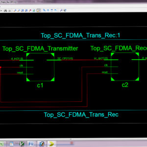
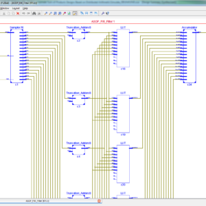
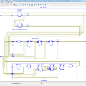
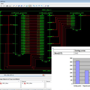
In functional and numerical analysis , a (DWT) discrete wavelet transform is any wavelet transform for which the wavelets are sampled discretely. In recent research of application of Image Processing there is a demand in high performance and efficient Discrete Wavelet Transform. This paper proposes the new design concept of high performance and efficient Discrete wavelet transform in order to overcome the problem faced in the recent research. The Truncation (MAC) multiply accumulate circuit based on the 2D-DWT is used in the proposed system of this paper, where the high pass and low pass FIR filters output are determined using the MAC. The existing system of DWT uses the concept of Floating point MAC which consumes larger area and its performance was low. Therefore, the proposed technique of DWT using Truncation MAC which achieves a better performance and reduces the area size when compared to existing Floating point MAC concept. The proposed DWT technique with Truncation MAC is implemented in the VHDL and synthesized in the XILINX and compared in terms of area, power and delay reports.
The Proposed Convolution Based Floating Point 2d-Dwt Architecture
In this section, convolution based floating point 2D-discrete wavelet transform architecture is proposed, which is designed with floating point multiply accumulate circuit (MAC) [21]. The MAC operation can be defined as multiplication and repeated addition. This means that the present multiplication result is added with previous MAC result (z[j] = z[j − 1] + (A[j].B[j]), where A[j] and B[j] are present input values, z[j] and z[j−1] are present and previous MAC results respectively.
Fig. 4(b) shows proposed 8-point floating point high pass filter (G1) for convolution based 2D-DWT. Here, one stage pipelined floating point MAC is used. If in = 0 then, MAC operations will be performed otherwise multiplication will be performed. The select lines s0 and s1 are used to select the proper inputs based on equations (3) to (5). During the row process of floating point 8×8-input in level 1, the equation (3), requires 12 clock cycles. So, during 1st, 2nd, 5th, and 9th clock cycles of row process in level 1, in = 1 and in = 0 during other clock cycles. Therefore, for each of 12 clock cycles of i th row for 8×8-input matrix of row process in level 1, the corresponding eni = 1 and others are 0 in 8 × 4 buffer as shown in Fig. 4(a). So, totally 96 clock cycles (12 × 8=96) are required to finish the row process of 8 × 8-point input matrix. During the row process of level 2, the equation (4) required 4 clock cycles. Here, in = 1 during 1st and 2nd clock cycles and in = 0 during other clock cycles. So, totally 16 clock cycles (4×4=16) are required to finish the row process. Here, f a0, f a1, and f a2 are the outputs of 4th column of HH1 4 × 4-buffer. If two floating point MACs are used in each filter of Fig. 3(b), then half of the above mentioned clock cycles will be reduced. This way of implementing convolution based floating point 2D-DWT requires less area/power than conventional design, where 4 floating point multipliers and 3 floating point adders are used for each low/high pass filter in row/column processes.
The number of floating point MAC operations in the first level of 1D-DWT is 3b2 4 , where b is the length of low/high pass filters. From the second level onward the number of MAC operations would be b2 4i−1 , where i ≥ 2. The total number of
floating point MAC operations (number of cycles) (N1D MAC ) required for the N-point 1D-DWT with L levels is shown in (6), where N = 2b. Similarly, the total number of floating point MAC operations (number of cycles) (N2D MAC ) required for the N × N-point 2D-DWT with L levels is shown in (8), where N = 2b. Here, the number of N-point sequences involved in row and column processes of the first level are N and N 2 respectively. The number of N 2i−1 -point sequences involved in the row and column processes of the i th level are N 2i−1 and N 2.2i−1 respectively, where i ≥ 2.
Advantages:
- High Efficiency
- Reduces Multiplier nxn=n bit Area size
- Reduces the size of IOB in 8-Bit
Reviews
There are no reviews yet.