Description
Proposed Title :
FPGA Implementation of Video Coding Standard with Efficient Streaming Deblocking Filter and SAO for HEVC Decoder
Improvement of this Project:
To design a High Efficiency method of Deblocking Filter and SAO Filter for HEVC Decoder in Block size of 32×32 and 64×64.
Software implementation:
- XILINX & MODELSIM
Existing System:
JOINT Collaborative Team on video coding formed by the ITU-T Video Coding Experts Group, and ISO/IEC Moving Picture Experts Group in 2010 has recently developed a new international video compression standard called high efficiency video coding (HEVC). It was finalized in January 2010 and it aims to reduce 50% bit rate in comparison with the existing advanced video coding (AVC) or H.264 high profile standard, with the same visual quality. Similar to the previous video coding standards it is also based on hybrid coding scheme which uses block-based prediction and transform coding. In H.264/AVC, a picture is divided into fixed size macro blocks of 16 × 16 samples but in HEVC, a picture is divided into coding tree units (CTUs) of 16 × 16, 32 × 32, or 64 × 64 samples. The CTU is further divided into smaller blocks using a quad tree structure; such a block is called a coding unit (CU). These CUs subsequently can be split into prediction units (PUs), and also act as a root of the transform quad-tree. Each of the child nodes of the transform quad tree defines a transform unit (TU). The size of the transforms used in the prediction error coding can vary from 4 × 4 to 32 × 32 samples, thus allowing transforms larger than in the paradigm of H.264/AVC.
In the coding scheme, block-based prediction and transform coding leads to discontinuities in the reconstructed signal at the block boundaries. Visible discontinuities at the block boundaries are known as blocking artifacts. A major source of blocking artifacts is the block-transform coding of the prediction error followed by coarse quantization. Moreover, in a motion-compensated prediction process, predictions for adjacent blocks in the current picture might not come from the adjacent blocks in the previously coded pictures, which can create discontinuities at the block boundaries of the prediction signal. Similarly, when applying intra prediction, the difference in the parameters of prediction process for adjacent blocks causes discontinuities at the block boundaries of the prediction signal. To reduce these blocking artifacts, two filter algorithms are used in HEVC which are applied sequentially to the reconstructed picture. Collectively they are called the in-loop filter (LF) algorithms, namely the Deblocking filter (DBF) and the sample adaptive offset (SAO) filter.
In coming years, consumer grade virtual reality (VR) headset shall occupy a major portion of the entertainment market and dominate the gaming industry. Since VR applicable devices such as mobile phones contain hardware video decoders that are tailored to resolutions used in a traditional video service like FHD or UHD, therefore it is important to build the hardware that fulfils the emerging VR requirements. These devices need 360◦ video services with a higher resolution, hence the traditional UHD leads to a major bottleneck in video streaming devices. The hardware systems designed to meet the emerging streaming demands need to exhibit high bandwidth, high throughput, and low power. Therefore, developing an efficient architecture on field programmable gate array (FPGA) and application specific integrated circuit (ASIC) is an important step before making commercial prototypes.
Several works have been reported on improving different aspects of throughput, area, and power. Dajiang et al. proposed a highly parallel DBF architecture for H.264 to process one macro-block in 48 clock cycles and give real time support to quad full high definition sequences at 60 frames/s at less than 100 MHz. The results when synthesized using 130-nm process cost a gate count of 30.2K. Zhou et al. proposed high-throughput and multi parallel very large-scale integration (VLSI) hardware architecture of the DBF for the HEVC. This architecture improves the performance at the expense of the slightly increased gate count as compared to the previously known architectures in HEVC. It supports an operating frequency of 278 MHz using 90-nm library and the real-time requirement of the DBF for 8K × 4K video format is 123 frames/s.
Shen et al. proposed four-stage pipeline hardware architecture on a quarter-large CU (LCU) basis with memory interlacing technique to increase the throughput, which can access the data in the process of both vertical and horizontal filtering efficiently. The design can support 4K × 2K at 30-frames/s applications at 28-MHz frequency. The same working group [9] proposed hardware architecture of combined DBF and SAO that was designed for the HEVC intraencoder, and proposed by simplified bit rate estimation method of SAO that can be applied to both intracoding and intercoding. This design can support ultrahigh definition (UHD) applications (7680×4320) at 40-frames/s and 182-MHz working frequency. Total logic gate count is found to be 103.3K using 65-nm library.
Zhu et al. proposed a HEVC in-LF architecture composed of fully utilized DBF and SAO. Due to pipeline the architecture achieved high throughput and synthesized frequency of 240 MHz. Hence it can process 3.84 Gpixels/s and support (7680 × 4320) @120 frames/s decoding. In the work of Ozcan et al. [10], is the first HEVC DBF hardware that uses two parallel data-paths in order to increase its performance. The results signify that the proposed hardware can decode full HD (1920 × 1080) at 30 frames/s. Srinivasarao et al. [11] proposed a new dual-standard DBF architecture, which supports both H.264/AVC and HEVC standards. The architecture takes 26 clock cycles for H.264/AVC and 14 cycles for HEVC to complete the filtering of a 16 × 16 pixel block. It occupies an area equivalent of 70.1K and frequency of operation is 100 MHz.
Cheng et al. proposed memory ping-pong and interlacing VLSI architecture to prevent DBF from unnecessarily waiting for pixels in both vertical and horizontal stages, which only takes 435 cycles at most to process a LCU of 64×64 pixels size. A four stage pipeline with a prefilter was proposed to eliminate the data dependency in the filtering process. This design can support 8K × 4K@90 frames/s real-time applications with operation frequency of 318 MHz at the cost of 62.9K gates. Diniz et al. proposed a DBF. It consumes 1027 clock cycles to complete the filtering of one 64×64 block at 140 MHz. ASIC implementation of the hardware architecture in 45-nm technology works at 200-MHz frequency and has a gate count of 3K. Furthermore, Hsu and Shen implemented a six-stage two lines 64×64 block pipeline architecture with low latency and high processing throughput. The ASIC implementation in 90-nm technology works at 100 MHz and the gate count was found to be 466.5K. It consumes 768 clock cycles. Shukla et al. and Peesapati et al. designed an area efficient dataflow architecture of SAO filter and a streaming DBF. The novelty of the proposed work used one set of four-edge filters for both horizontal and vertical filtering along with SAO filter. In, two set of four-edge filters were used. This paper reduces the area compared to [18] at the little increase of processing clock cycles. This paper also proposes the use of multiple SAO filters in a pipeline approach along with DBF. The proposed hardware architecture presents a novelty over previous architectures in terms of processing clock cycles with an increase in area. The proposed design gives high throughput for UHD video sequences.
Disadvantages:
- Number of Stage based pipelined architectures
- Less Throughputs
- More Area and delay
Proposed System:
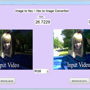
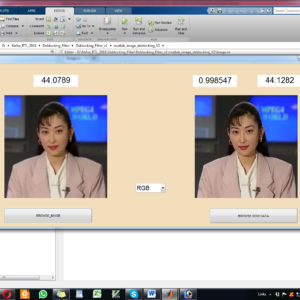
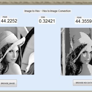
This paper presents a FPGA Implementation of mixed pipelined architecture and parallel processing for Deblocking filter and SAO architecture in High Efficiency Video coding (HEVC) standard. In this paper aims to developed HEVC architecture in low latency with increase throughput and reduce the number of processing cycles with using Edge filtering method of modified Horizontal and Vertical Boundaries. This proposed work will presents mixed pipeline architecture and conditions based filter decisions with multiple coding tree units on size 64×64, 32×32, 4×8, 8×4 block sizes. This proposed work is implemented on Field Programmable Gate Array (FPGA) platforms and compared with state of the literature and conclude the proposed work with 64×64 block size is suitable for all consumer High Definition applications, finally this design developed in Verilog HDL and synthesized in Xilinx Vertex FPGA XC5VFX200T-2FF1738 and compared all the terms of area, delay and power.
In the proposed architecture, a video frame is partitioned into 36×36 blocks. Fig. 1 shows the flowchart for filtering process of each 36×36 block. Each 36×36 block is first divided into nine 4×36 blocks. These 4×36 blocks are then filtered by taking four edge filters in parallel, to filter the four edges of adjacent 4×8 blocks shown in Fig. 2. Four edges present in each 4×36 block are filtered using edge filters and then stored in temporary buffers of size 4×36 in a pipelined manner. As shown in Fig. 3 the proposed architecture consists of an input buffer for storing input samples of different blocks, edge filters for parallel filtering operations, temporary buffers for pipeline, transpose memory for storing the transposed block, and output buffers for storing the filtered samples of the block. The input samples of a CU (32×32) are processed from the input RAM. During the same clock period, the filtering parameters are taken from the input buffer. The proposed architecture works in a streaming fashion. Each block is processed in the form of row sample grid. One sample grid consists of 4×36 block at a time and four vertical edge filters (horizontal) are used in parallel for filtering two adjacent 4×8 blocks present in one 4×36 block. Parallel operation is performed because filtering the edge of one adjacent 4×8 block is independent of filtering of the other edges. This operation is performed in all nine 4×36 blocks in a pipelined fashion. The advantage of using a 36×36 block is that the CU block needs to store its last 32×4 column in some temporary buffer in order to filter the edge present between the last 32×4 column of the CU block and the first 32×4 column of the next CU block. Moreover, an extra edge filter is required for filtering this edge. This results in an increase in the utilization of resources with an additional delay. Hence, to remove this complexity, the CU is transformed to 36×36 block. So that the last 36×4 column is filtered in the block itself nullifying the consideration of the last 36×4 column of the current block for filtering the next CU block. The CU of other sizes are also transformed in the same way, viz. 8×8 is transformed to 12×12, 16×16 is transformed to 20×20 and 64×64 is transformed to 68×68, respectively. The obtained 4×36 blocks are transposed to 36×4 blocks and stored in block buffer (36×36). The block buffer stores nine such blocks resulting in a 36×36 block output.
The 4×36 blocks are accessed from the block buffer using a control unit which generates the select input for the multiplexer (MUX). The multiplexer selects each 4×36 for horizontal filtering. Separate units of edge filters and transpose blocks are used for vertical edge (horizontal) filtering and horizontal edge (vertical) filtering respectively.
Similar processing steps have been carried out for filtering the 4×36 blocks of vertical filtered block. The filtered 4×36 blocks are obtained in pipelined fashion and transposed again to get back the filtered samples. These filtered samples are obtained from the output buffer that can be read from the output RAM. The same vertical filter can be used for performing the horizontal filtering with a trade-off of higher amount of delay and lesser amount of resources. However, the focus of this work is to increase the processing speed.
Hence, multiple edge filters and multiple transposes have been used for filtering operation. The DBF hardware is processing entire LCU in the form of proposed CU (32×32) block where it consists of luminance and chrominance components (Cb and Cr). The advantage of this architecture is to process the luma input followed by chroma with the same size CU (32×32) for YUV 4:2:0 format. The next subsections explain individual modules of DBF hardware.
Deblocking Filter:
The DBF is applied at the edges of all the 8 × 8 luma and chroma samples which are adjacent to a PU or TU boundary with the exception when the DBF is disabled across slice/tile or frame boundary. Both PU and TU boundaries are included because PU boundaries are not always aligned with the TU boundaries in some cases of interpicture predicted coding blocks (CBs). The syntax elements that control the DBF across the slice and tile boundaries are situated in sequence parameter set, picture parameter set (PPS), and slice headers. In HEVC, the DBF is applied to the edges that are aligned on an 8 × 8 sample grid for both luma and chroma samples instead of a 4 × 4 sample grid basis as used in H.264/AVC. This restriction reduces the worst case computational complexity without noticeable degradation of the image visual quality. It also helps in improving parallel processing operation by preventing cascading interactions between nearby filtering operations. DBF operation can be broadly analyzed in three stages.
1) Boundary strength (BS) calculation on filter edge.
2) Filtering decision.
3) Filtering (vertical/horizontal) operation.
Advantages:
- Mixed pipelined architectures
- More Throughputs
- Less Area and delay
” Thanks for Visit this project Pages – Buy It Soon “
Design and Implementation of Efficient Streaming Deblocking and SAO Filter for HEVC Decoder
“Buy VLSI Projects On On-Line”
Terms & Conditions:
- Customer are advice to watch the project video file output, before the payment to test the requirement, correction will be applicable.
- After payment, if any correction in the Project is accepted, but requirement changes is applicable with updated charges based upon the requirement.
- After payment the student having doubts, correction, software error, hardware errors, coding doubts are accepted.
- Online support will not be given more than 5 times.
- Extra Charges For duplicate bill copy. Bill must be paid in full, No part payment will be accepted.
- After payment, to must send the payment receipt to our email id.
- Powered by NXFEE INNOVATION, Pondicherry.
Payment Method:
- Pay Add to Cart Method on this Page
- Deposit Cash/Cheque on our a/c.
- Pay Google Pay/Phone Pay : +91 9789443203
- Send Cheque through courier
- Visit our office directly
International Payment Method:
- Pay using Paypal : Click here to get NXFEE-PayPal link
Bank Accounts
HDFC BANK ACCOUNT:
- NXFEE INNOVATION,
HDFC BANK, MAIN BRANCH, PONDICHERRY-605004.
INDIA,
ACC NO. 50200013195971,
IFSC CODE: HDFC0000407.