Description
A Real-Time FHD Learning Based Super Resolution System Without a Frame Buffer
Existing System:
SINGLE image super-resolution (SR) aims to generate high-resolution (HR) images from low-resolution (LR) images. It is a well-known, ill-posed problem since a single HR image could generate more than one LR image, and it requires enough prior knowledge to reconstruct the high quality HR images. To solve this problem, learning-based single-image SR methods have achieved outstanding performance and gained state-of-the-art results, by learning from millions of external image patches.
In this brief, a learning-based regression super-resolution architecture without using a frame buffer is proposed. we implement the system with 128 learned dictionaries on a field programmable gate array (FPGA). This system can achieve output resolution of 1920 × 1080 (FHD) at 60 fps using only numbers of line buffers.
Review of Super Resolutions:
This section illustrates the development of the example based and dictionary learning-based single-image super resolution algorithms. Different from using information of only the input testing image, example-based SR algorithms use knowledge from plenty of external HR and LR example image pairs to help generate output HR images. A classic example-based SR work was proposed by Freeman et al. Chang et al. proposed a neighbor embedding method which assumes the local structure similarity of LR and HR patches’ manifolds. The output HR image patch shares the same weight in its HR manifold as the input LR image patch in its local LR manifold. A reconstruction method such as locally linear embedding, proposed by Roweis and Saul, has also been used for getting fairly good results.
Yang et al. [5] takes sparsity prior into consideration using sparse coding over learning representative HR and LR patches jointly called a dictionary. Compared to Chang et al., Yang et al. reduces the targeting candidates from numerous training patches to certain numbers of points in a dictionary, achieving encouraging results. However, the computation complexity takes quite a lot of time to resolve the sparse coding online while testing each patch input. Zeyde et al. [6] optimized the overall framework by means of the K-SVD algorithm [7]. They learned LR and HR dictionaries separately by obtaining the LR dictionary first and then generating the HR dictionary from the LR dictionary with sparse coding. There are great improvements in both the testing time and quality of resulting images in their work.
SINGLE IMAGE SUPER-RESOLUTION:
Single image SR is the method to increase resolution from only single image LR input. The reconstruction step is simple and can achieve faster processing algorithm than multiple image SR. In the followings, we explain reference algorithm, bi-cubic interpolation and sparse representation.
Bi-cubic Interpolation Base Method
Bi-cubic interpolation was firstly proposed in with several variations to increase the performance. The general weakness of this approach is the blur on the edge and corner of the image as the result of integrating sharpening and smoothing process. Moreover, research applied back projection kernel p to increase the image resolution by using LR error, as shown in (1), in which LR image is Y, HR image is X and with iteration t. However, it still has chessboard and ringing effect on the reconstructed image.
Image super-resolution via sparse representation
The concept of method is to reconstruct LR image combine with blurred image, H , and down-sampled image, S resulting in the HR image, as shown in (2).
By using this method, it uses dictionary coefficient from the trained image data and patch processing to learn the relation between LR and HR images. After that, HR is reconstructed from sparse representation with dictionary coefficient. This method can improve resolution quality but has more processing time.
Disadvantages:
- Very low PSNR, SSIM in Bi-cubic Interpolation
- Area, Delay and Power will take more
Proposed System:
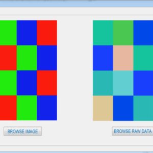
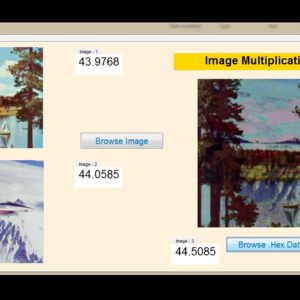
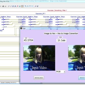
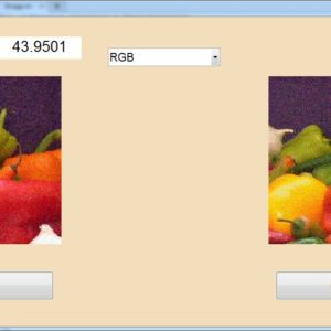
The main aim of the Single image (SR) super-resolution is to generate (HR) high-resolution images from (LR) low-resolution images. This paper briefly presents a concept of real time super resolution method of FHD based image extended and scaling processor. The super resolution system includes three blocks of operations. The first is a low-frequency interpolation stage, where bicubic interpolation is used for reconstructing the low-frequency parts of HR images. The second stage generates high-frequency patches by choosing the highest related pre-trained regression function according to each HR low frequency patch. In the third stage, with the high-frequency information, the low-frequency image patches are enhanced and overlapped to construct the SR result. These operations for gaining a high-frequency result are applied to the Y-luminance channel only, while the high-resolution Cb and Cr channels are generated by bicubic interpolation. The proposed system generates the output image resolution of 1920 X 1080 (FHD) by the input of 800 X 800 image size. The proposed architecture performs an anchored neighborhood regression algorithm that generates a high-resolution image from a low-resolution image input using only numbers of line buffers. Finally, super resolution technique is implemented in VHDL and Synthesized in the XILINX VERTEX-5 FPGA and shown the comparison for power, area and delay reports.
IMPLEMENTATION:
Fig. 1 shows that there are three main stages in the proposed system. The first is a low-frequency interpolation stage, where bicubic interpolation is used for reconstructing the low-frequency parts of HR images. The second stage generates high-frequency patches by choosing the highest related pre-trained regression function according to each HR lowfrequency patch. In the third stage, with the high-frequency information, the low-frequency image patches are enhanced and overlapped to construct the SR result. These operations for gaining a high-frequency result are applied to the Y-luminance channel only, while the high-resolution Cb and Cr channels are generated by bicubic interpolation. In the second stage, which is the core of this system, those blocks handling massive computation, such as “Principal Component Analysis (PCA) Dimensionality Reduction” and “High-Frequency Patch Generation,” introduce long latency for processing. Therefore, the operating frequency of the entire system is limited, further restricting the output resolution. To solve this problem, the proposed SR architecture doubles the operation period in the second stage, and the system is then designed with multiple clock domains. This is realized by making use of the available pixel time slots owing to the overlap stride while extracting features of patches.
Data Flow and Memory Usage:
Fig. 2 is the data flow of the proposed architecture and its clock domain partition. Memory not only buffers the line data but also separates the different clock domains. Fig. 4 shows the bi-cubic interpolation operation. 16 integer pixels can interpolate 4 different fractional pixels by using 4 different bicubic interpolation weights. The first and second operation in Fig. 4 generate the first line data, and the third and fourth operations in Fig. 4 generate the second line data. In a bicubic kernel, inputting four pixels of four consecutive lines from line buffers, we get one bicubic interpolated pixel output. Fig. 3 shows the read/write timing of bicibic memory. In bicubic memory, five line buffers are needed. While one line buffer is used for memory write by the input low resolution image, the other four line buffers are used for memory read to the bicubic kernel. In one external line period, which is indicated by low resolution Hsync signal, the bicubic memory will be read twice, which is indicated by high resolution Hsync signal. Notice that these two reading line data are the same, but the bicubic coefficients are different to interpolate two different lines, as shown in Fig. 3.
After scaling up by bi-cubic interpolation, pixels are converted from RGB color space to YCbCr color space. Only the Y channel will be processed by the stage-two subsystem, while the Cb Cr channel will be temporarily stored into the Cb, Cr pipeline buffer as shown in Fig. 1. The Y channel data of bi-cubic interpolation data is then written into patch memory, which is composed of 12 line buffers. Fig. 5 shows the scheduling of patch memory read/write. There are two line buffers for the input Y channel. That is, we update two lines of the patch memory from the bi-cubic kernel output for each line scan of the input LR image. Fig. 6 shows the architecture of feature extraction, which has four different kernels, including the horizontal gradient kernel, vertical gradient kernel, horizontal laplacian kernel, and vertical laplacian kernel. Due to the vertical laplacian kernel, which is the largest vertical kernel, we need four additional line buffers for top and bottom, and ten lines in total are required to generate 6×6 feature patches. After the feature extraction block, the 144-dimensional (6×6×4) feature passes through the PCA dimensionality reduction block to geneate a 28-dimensional feature vector, as shown in Fig. 1. Next, in the Dictionary Correlation Computation block shown in Fig. 1, we use this low-dimension feature vector to search the nearest anchor by computing the correlations between the input vector and those in the dicionary. Finding the index of the one with the highest correlation, we get the corresponding regressor in the form of project matrix, from the dictionary ROM, which stores 128 projection matrices. Computing the matrix multiplication of the low dimension feature and projection matrix, we get the high frequency patch in the Regression Mapping block shown in Fig. 1. Finally, adding the low frequency patch and high frequency patch, we get the 6×6 super-resolution patch. The super resolution patch will be written into the overlap memory in the Overlapped Patch Reconstruction block in Fig. 1. Fig. 7 shows the scheduling of overlap memory read/write. Between neighboring patches, there is a two-pixel stride in both the horizontal and vertical directions. In a patch scan line period, we will read out two lines of data. Fig. 8 shows the patch overlapping process. Each data point will be overlapped by 9 different super-resolution patches, but this does not include the boundary condition output pixel. By averaging the corresponding 9 pixel values from these 9 patches, the final Y-channel value of each pixel is constructed. The Cb, Cr line buffer shown in Fig. 2 buffers the data of the Cb, Cr channel. Since there is a 12-line delay between the output of the Y channel and the output of the bicubic kernel, we need 12 line buffers to store the Cb/Cr channel data. Finally, the Y channel data output from the overlap memory together with the Cb/Cr channel output from the Cb/Cr pipeline buffer will be converted to the RGB domain. As the output of this system, the RGB pixels form the high-resolution super-resolution image.
As previously described, we assume LR image is a part of HR image. The proposed method needs to keep information of the LR image to reconstruct HR image for real time hardware processing. We propose algorithm based on Bi-cubic Interpolation to minimize the processing time but at the same time, to improve the reconstructed image quality as well. Our proposed method named overlapping bi-cubic interpolation updates the different new LR image with the original LR image to HR image.
The demand of the digital image processing technology from the social different domain growing at present day by day, some complex and effective algorithms of imagery processing related domain have been proposed. Usually, there are mainly two methods [1] to raise the imagery processing speed. First, carry on the optimization to the imagery processing algorithm. Simplifies the algorithm to raise the running speed of the algorithm, but the precision is very difficult to guarantee. Second, change the way to realize the algorithm. Considered the convenience and the cost, the imagery processing algorithm is realized generally with the form of software programming. The processing speed meets the timely need difficulty, because of standard serial processing method. The imagery processing speed can be raised, and the high speed [2] requirements can be met by the way of the software and hardware design for the algorithm which is simple structure, large quantity data and parallel character. FPGA, which is programmable logical component, not only has the characteristic of big scale, high integration rate and high reliable as ASIC, but also maintained the characteristic of short design cycle, lowly development invested and high flexibility as PLD. The central processors (CPU), the multiplier, the digital processor (DSP)[3] have been integrated in new generation FPGA. DSP are unable to compare with the hardware parallel processing and the stream line operation of FPGA. Therefore the application of FPGA in the digital image processing domain is quite ideal choice.
Bi-Cubic computation module:
We know that calculating the value of an interpolation picture element need carry on the level and the vertical convolution operation of 16 spots picture element 4×4 matrices according to the introduction of the Bi-cubic interpolation enlargement algorithm. The value of a temporary reference spot can be obtained by convolution operation from 4 picture element with the respective weight value in the horizontal direction. The value of an interpolation picture element can be obtained by the second convolution operation from the values of direction four temporary reference spots with the respective weight value again in the vertical direction. The independent D trigger, the multiplier and the accumulator will be used in the traditional design in such computation, in, will use realizes. The arithmetic circuit will be numerous and diverse. The weight h can be calculated and obtained by search table way of the Bi-cubic interpolation enlargement algorithm which is improved as 2.2 in this paper. Realize the Bi-cubic interpolation enlargement algorithm by ALTMULT_ADD, LPM_MULT, PARALLEL_ADD which are provided by LPM of Xilinx Vertex 5 FPGA.
The ALTMULT_ADD,LPM Multiplier, can set the input port number, the bit width of data and the clock control by the user needs. The module can carry out the multi-port multiplication respectively and add the calculated results of various quarters as the output.
The LPM_MULT, LPM multiplier, can greatly improve the efficiency and performance of the multiplication. After setting parameters simply, it can complete the tow-way multiplication between the data with signed and unsigned. It also can complete the multiplication between the signal square summation input and the constant. The witch of the input can be automatically calculated. The difficulty of the design becomes simple.
The PARALLEL_ADD,LPM parallel adder, can be defined the number of input ports for the multiplication and the witch of data according to the user needs. The module can add separate data parallel and automatically generate the output data bit witch to meet the requirements. The user also can improve the performance by adding the displacement function of registers and line control. The convolution operation in four horizontal direction of the pixel matrix is completed by four multipliers in this article. Then the four calculation results multiply with their respective weight in the corresponding LPM_MULT. Finally, the convolution operation in the vertical direction is completed through the parallel adder. The interpolated points can be as output. The whole process of the calculation is shown in Figure 1. Shown in Figure1, the box stands for the ALTMULT_ADD in the fourth row of the four row convolution operation on the horizontal direction. Its input port dataa_0[7..0] connects to output port of the data cache module taps0x.It receives all the values of the fourth line(P9ǃP10ǃP11 and P12) of the 4 4 × pixel matrix and has a displacement.
Advantages:
- Increases the PSNR, SSIM Level in Bi-Cubic Interpolation
- Reduced the Area, Delay and Power
” Thanks for Visit this project Pages – Buy It Soon “
A Real-Time FHD Learning Based Super Resolution System Without a Frame Buffer
“Buy VLSI Projects On On-Line”
Terms & Conditions:
- Customer are advice to watch the project video file output, before the payment to test the requirement, correction will be applicable.
- After payment, if any correction in the Project is accepted, but requirement changes is applicable with updated charges based upon the requirement.
- After payment the student having doubts, correction, software error, hardware errors, coding doubts are accepted.
- Online support will not be given more than 5 times.
- Extra Charges For duplicate bill copy. Bill must be paid in full, No part payment will be accepted.
- After payment, to must send the payment receipt to our email id.
- Powered by NXFEE INNOVATION, Pondicherry.
Payment Method:
- Pay Add to Cart Method on this Page
- Deposit Cash/Cheque on our a/c.
- Pay Google Pay/Phone Pay : +91 9789443203
- Send Cheque through courier
- Visit our office directly
International Payment Method:
- Pay using Paypal : Click here to get NXFEE-PayPal link
Bank Accounts
HDFC BANK ACCOUNT:
- NXFEE INNOVATION,
HDFC BANK, MAIN BRANCH, PONDICHERRY-605004.
INDIA,
ACC NO. 50200013195971,
IFSC CODE: HDFC0000407.