Description
Proposed Title :
FPGA Implementation of High Speed and Highly Reliable World Fastest FFT Architecture
Improvement of this Project:
To design a 16-point radix-22 fully parallel FFT as per base paper architecture and 2048-point Split Radix FFT for proposed development and finally compared all the terms of area, delay and power.
Software implementation:
- XILINX & MODELSIM
Existing System:
WITH the increasing demand on throughput of current signal processing applications, pipelined parallel FFT architectures have become very popular in the last years. These architectures are able to process a continuous data flow of several samples in parallel. The main types of parallel pipelined FFTs are multi-path delay commutator (MDC) and multi-path delay feedback (MDF). Both of them allow for high throughput in the range from hundreds of mega samples per second (MS/s) to tens of giga samples per second (GS/s). In this work, we aim for the highest possible throughput. In order to achieve it, we consider the use of fully parallel FFTs. These architectures calculate an N-point FFT in a continuous flow of P = N samples in parallel. Thus, they correspond to the direct implementation of the FFT flow graph, i.e., each addition/rotation in the flow graph is directly translated into an adder/rotator in hardware. This represents the maximum parallelization that an N-point FFT can have. Fully parallel FFTs are already used in applications such as compensation of chromatic dispersion inherent in optical fibers and radar. For compensation of chromatic dispersion, filters with samples rates of tens of GS/s are required. The filter length scales more or less linearly with the fiber length. Therefore, for long fibers, hundreds or even thousands of taps are required. An efficient way to implement these filters is to make use of fully parallel FFTs. For radar applications, the high throughput of fully parallel FFTs allow for object detection over large bandwidths. Another area of interest of fully parallel FFTs is for applications where iterative FFTs are implemented. Note that in iterative FFTs, the butterfly of the processing element (PE) usually consists of an r-point fully parallel FFT, where r is the FFT radix. For high radices, a hardware-efficient fully parallel FFT can reduce significantly the hardware cost of the PE in the iterative FFT. Finally, given the high demands of 5G systems due to the use of multiple antennas, fully parallel architectures could be potentially used in future communication systems. Although fully parallel FFTs have been known for a long time, no previous work in the literature addresses in detail the technical challenges of designing fully parallel FFT architectures.
A first technical challenge is the implementation of the rotators as shift-and-add operations. The high parallelization of fully parallel FFTs demands the use of a large number of rotators. Without a proper design of these rotators, the area of the FFT can increase considerably. The fact that all rotators in a fully parallel FFT rotate by a constant angle allows for using advanced shift-and-add constant multiplication techniques to minimize their resource complexity. In our approach, we exploit the use of existing methods for constant multiplications, including single constant multiplication (SCM), multiple constant multiplication (MCM) and constant matrix multiplication (CMM). With the aim of designing the most efficient rotators, we also exploit different approaches to implement rotators in hardware. A second challenge related to the design of the rotators is the accuracy of the FFT calculations. Here, the coefficient selection plays an important role in the design of rotators. A good coefficient selection results in coefficients that calculate accurate rotations using few adders [34]. This guarantees high accuracy for the entire FFT.
A third challenge related to rotations is the selection of the FFT algorithms. FFT algorithms based on the Cooley-Tukey approach only differ in the rotations at different stages. A good selection of the FFT algorithm will reduce the number of rotations and, therefore, the area of the FFT architecture. A fourth challenge in the design of very high-throughput FFTs is pipelining. High throughput demands deep pipelining. However, with the high parallelization of fully parallel FFTs, pipelining increases the area of the FFT. In order to minimize the amount of pipelining, we have taken into account the depth of the rotators in the FFT. As a result, our rotators only require three clock cycles to calculate the rotations, achieving a critical path of only one adder. This not only increases the clock frequency, but also keeps the pipelining at reasonable levels. A final challenge is the generation of the FFT architectures automatically. This challenge is a consequence of the implementation of the rotators as shift-and-add. Due to the large number, complexity and variety of rotators, it is unfeasible to implement them by hand or using the generate command in VHDL. As a result, it is needed to create a tool that generates the architectures automatically.
Figure 1 shows the flow graph of a 16-point radix-22 FFT according to the Cooley-Tukey algorithm, decomposed using decimation in frequency (DIF) [35]. The FFT consists of n = log2 N stages. At each stage s ∈ {1,…, n} of the graph, butterflies and rotations are calculated. The lower edges of the butterflies are always multiplied by −1. These −1 are not depicted in order to simplify the graphs.
The numbers at the input represent the index of the input sequence, whereas those at the output are the frequencies, k, of the output signal X[k]. Finally, each number φ in between the stages indicates a rotation by:
Wφ N = e−j 2π N φ. (2)
As a consequence, samples for which φ ∈ {0, N 4 , N 2 , 3N 4 } must be rotated by 0◦, 270◦, 180◦ or 90◦, which corresponds to complex multiplications by 1, − j, −1 and j, respectively. These rotations are considered trivial, because they can be carried out by interchanging the real and imaginary components and/or changing the sign of the data.
Different radices only differ in the rotations at the FFT stages, whereas the butterflies are the same. The most common algorithms are radix-2, radix-22, radix-23 and radix-24 in their decimation in time (DIT) and DIF versions. For a fully parallel FFT we also consider the split radix algorithm. The advantage of split radix is its smaller number of non-trivial rotations, whereas the advantage of radices of 2k , k ≥ 2 is that some of their stages only include trivial rotations.
Disadvantages:
- More Delay
- Less Efficiency
- No Burst Mode Data Transfer
Proposed System:
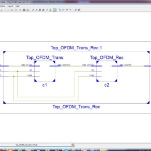
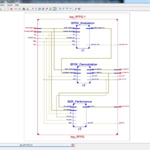
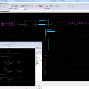
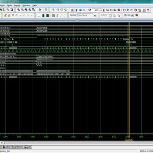
This paper present a Reliable High seed communication of Fast Fourier Transformer (FFT) hardware architecture, which present break the barrier of 100 GS/s on FFT calculation. This FFT algorithm will have a highest throughput in current signal processing applications but it have barrier and pipelined complexity so it will increases multi-path delay commutate and multi path delay feedback in signal transmission and reception part. In this work will achieve the highest throughput in FFT algorithm with using Cooley Tukey approach of radix 22 16-point parallel FFT and IFFT method, here the proposed architecture will increases pipelined in parallel 16-point FFT architecture and reduced the barrier in high speed FFT and IFFT Communications. Finally this work will implemented in VHDL and simulated in Modelsim with Synthesize in Xilinx 14.2 and compared all the parameters in terms of area, delay and power.
PROPOSED FULLY PARALLEL FFT ARCHITECTURES:
Fig. 2 shows the proposed 16-point radix-22 fully parallel FFT architecture. This architecture is a direct implementation of the FFT flow graph in Fig. 1 in the sense that each addition in the flow graph is translated into an adder and each rotation into a rotator. The architecture consist of butterflies, delays (D) and rotators. Contrary to other FFT architectures, fully parallel FFTs do not include circuits for data management. However, it involves other design challenges related to the design of the rotators, the selection of the FFT algorithms and the implementation in VHDL. Next section present these challenges, as well as the proposed solutions.
Design of the Rotators
In fully parallel FFTs, rotators take the largest part of the area. As they consist of constant multiplications, the best way to reduce the area of the FFT is to implement them as shift-and-add. Low-depth shift-and-add implementations also reduce the number of adders in series in the rotators. This reduces the amount of pipelining required for high-throughput. Furthermore, the accuracy of the rotators has effect in the accuracy of the entire FFT. In order to achieve accurate FFTs it is necessary to select coefficients with small rotator error. To achieve these goals, we take into account the coefficient selection, we explore different architectures for the rotators and we make use of advanced shift-and-add algorithms. The details are explained next.
Split Radix FFT:
In general, all the FFT processors can be categorized into two main groups: pipelined processors or shared-memory processors. Examples of pipelined FFT processors. A pipelined architecture provides high throughputs, but it requires more hardware resources at the same time. One or multiple pipelines are often implemented, each consisting of butterfly units and control logic. In contrast, the shared-memory-based architecture requires the least amount of hardware resources at the expense of slower throughput. In the radix-2 shared-memory architecture, the FFT data are organized into two memory banks. At each clock cycle, two FFT data are provided by memory banks and one butterfly unit is used to process the data. At the next clock cycle, the calculation results are written back to the memory banks and replace the old data. The scope of this brief is limited to the shared-memory architecture.
In the shared-memory architecture, an efficient addressing scheme for FFT data as well as coefficients (called twiddle factors) is required. For split-radix FFT, it conventionally involves an L-shaped butterfly data path whose irregular shape has uneven latencies and makes scheduling difficult. In this brief, we show that the SRFFT can be computed by using a modified radix-2 butterfly structure. Our contribution consists of mapping the split-radix FFT algorithm to the shared-memory architecture, leveraging the lower multiplicative complexity of the algorithm to reduce the dynamic power and developing two novel twiddle factor addressing schemes for the split-radix FFT.
Advantages:
- Less Delay
- More Efficiency
- Burst Mode Data Transfer
” Thanks for Visit this project Pages – Buy It Soon “
World’s Fastest FFT Architectures: Breaking the Barrier of 100 GS/s
“Buy VLSI Projects On On-Line”
Terms & Conditions:
- Customer are advice to watch the project video file output, before the payment to test the requirement, correction will be applicable.
- After payment, if any correction in the Project is accepted, but requirement changes is applicable with updated charges based upon the requirement.
- After payment the student having doubts, correction, software error, hardware errors, coding doubts are accepted.
- Online support will not be given more than 5 times.
- Extra Charges For duplicate bill copy. Bill must be paid in full, No part payment will be accepted.
- After payment, to must send the payment receipt to our email id.
- Powered by NXFEE INNOVATION, Pondicherry.
Payment Method:
- Pay Add to Cart Method on this Page
- Deposit Cash/Cheque on our a/c.
- Pay Google Pay/Phone Pay : +91 9789443203
- Send Cheque through courier
- Visit our office directly
International Payment Method:
- Pay using Paypal : Click here to get NXFEE-PayPal link
Bank Accounts
HDFC BANK ACCOUNT:
- NXFEE INNOVATION,
HDFC BANK, MAIN BRANCH, PONDICHERRY-605004.
INDIA,
ACC NO. 50200013195971,
IFSC CODE: HDFC0000407.